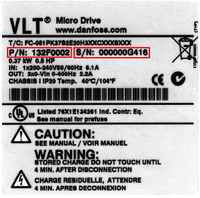
Danfoss VLT micro drive FC 51 Name Plate
🔍 Wondering what the specifications on the Danfoss VLT Micro Drive FC 51 nameplate mean?
This guide provides a detailed breakdown of each specification, helping HVAC professionals, industrial electricians, and automation engineers understand and interpret the key data for optimal performance.
📌 What You’ll Learn:
✔️ Complete list of specifications found on the FC 51 nameplate,
✔️ How to read and interpret voltage, frequency, power ratings & more,
✔️ Importance of each parameter in real-world applications,
✔️ Best practices for selecting the right drive based on nameplate data,
🙏Welcome to Insight Control System blog page📖
Basic Overview:
- The Danfoss VLT Micro Drive FC 51 is a compact and cost-effective Variable Frequency Drive (VFD) used to control the speed of AC motors.
- The Danfoss VLT micro drive FC 51 Variable Frequency Drive is an electronic device that regulates the speed and torque of an electric motor by changing the frequency and voltage supplied to it.
- It is widely used in industrial applications to control the speed of pumps, fans, conveyors, compressors, and other components, thereby saving energy and improving system performance.
Features:
- Designed to fit in small spaces with minimal installation requirements.
- It Can operate in harsh environments with high efficiency.
- Reduces power consumption by adjusting motor speed as needed.
- Built-in Motor Protection: Prevents overload and extends motor life.
- Ensures smooth operation even if the motor is already running.
- Comes with a simple user interface and an intuitive keypad.
- Integrated PID Controller: Allows for automatic process control without external controllers.
- Coated Printed Circuit Boards: Protects against dust and humidity for better durability.
- Brake Chopper (Optional): Helps control deceleration in applications requiring quick
stopping.
 |
| Nameplate sticker |
- The nameplate sticker is located on the top of each VFD drives and shows the ratings, serial number, warnings catalog number, and other relevant data for each unit.
- This nameplate sticker is mostly the same in the VLT model VFD drives, with only a few changes in the some VLT model VFD drives.
1st ROW: (TYPE CODE)
Position
1 - 3 [FC]- is Product group,
Possible choice is: Frequency converters,
Position 4 - 6 [051] is Series and product type,
Possible choice is: Micro Drive,
Position 7 - 10 [P] is Power size,
Possible choice is: 0.18 to 22 kilo watt.
Position 11 - 12 [S2] is Mains voltage,
Possible
choice is:
- S2 that means Single phase 200 to 240 Volt AC,
- T2 that means 3-phase, 200 to 240 Volt AC,
- T4 that means 3-phase, 380 to 480 Volt AC,
Position 13 - 15 [E20] is Enclosure,
Possible choice is: IP20/Chassis,
Position 16 - 17 [H3] is RFI filter,
Possible choice is:
- HX - that means No RFI filter,
- H1 - that means RFI filter class A1/B,
- H3 - that means RFI filter A1/B reduced cable length 1,
Position 18 [X] is Brake,
Possible
choice is:
- B - that means Brake chopper included (from 1.5 kilo watt and up),
- X - that means No brake chopper included.
Position 19 [X] is Display,
Possible
choice is:
- X - that means No Local Control Panel,
- N - that means Numerical Local Control Panel,
- P - that means Numerical Local Control Panel with potentiometer,
Position 20 [C] is Coating PCB,
Possible
choice is:
- C - that means Coated PCB,
- X - that means No coated PCB,
Position 21 [X] is Mains option,
Possible choice is No mains option,
Position 22 [X] is Adaptation A,
Possible choice is No adaptation,
Position 23 [X] is Adaptation B,
Possible choice is No adaptation,
Position 24 - 27 [SXXX] is Software release,
Possible choice is Latest release - standard software,
2nd ROW:
 |
| Serial Number |
P/N 132F0002 is the drive code
number.
S/N:000000G416 is the drive serial number.
The last 3 digits Indicate the week and year that the unit was built, for (e.g) 416,
41 is week and 6 is year that means 2016,
3rd ROW:
 |
| Power Rating |
0.37 kW 0.5 HP is the drive Power rating.
4th ROW:
 |
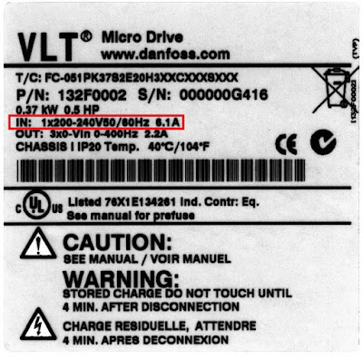
| Input Voltage |
IN: 1x200-240V 50/60Hz 6.1A is the drive input voltage, frequency and current,
5th ROW:
 |
| Output Voltage |
OUT: 3x0-Vin 0-400Hz 2.2A is the drive output voltage, frequency and current.
6th ROW:
 |
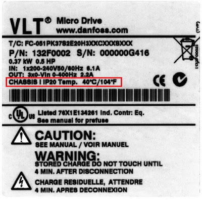
| Drive Chassis |
CHASSIS I IP20 Temp. 40°C/104°F is the drive chassis IP rating and drive Temperature.
SYNBOLS:
 |
| Symbols |
The 1st
symbol is representing CE conformity.
The 2nd
symbol is representing Restriction of Hazardous
Substances.
The 3rd
symbol is representing Underwriters Laboratories.
The 4th
symbol is representing CAUTION:
Below the caution, it is mentioned to refer to the drive manual.
The 5th
symbol is representing WARNING:
Below the warning is an indication of the discharge time.
The 6th symbol is representing Disposal instruction:
- Equipment containing electrical components must not be disposed of together with domestic waste.
- It must be separately collected with electrical and electronic waste according to local and currently valid legislation.
Note:
Removing the labels from the VLT Common AC Drive Modules can result in loss of warranty.
Qualified Personnel:
- The frequency converter must be transported, stored, installed, operated, and maintained correctly and reliably to function properly and safely.
- Only qualified individuals may install or operate this equipment.
- Qualified personnel are qualified professionals who are authorised to install, commission, and maintain equipment, systems, and circuits in conformity with applicable rules and regulations.
- Furthermore, qualified workers must be conversant with the instructions and safety precautions mentioned in these operating instructions.
WARNING:
 |
| Warning |
Safety Symbols:
- Indicates a potentially hazardous situation that could result in death or serious injury.
High Voltage:
- Frequency converters contain high voltage when connected to AC mains input, DC supply, or load sharing.
- Failure to perform installation, start-up, and maintenance by qualified personnel can result in death or serious injury.
- Installation, start-up, and maintenance must be performed by qualified personnel only.
Unintended Start:
- When the frequency converter is connected to AC mains, DC supply, or load sharing, the motor may start at any time.
- Unintended start during programming, service, or repair work can result in death, serious injury, or property damage.
- The motor can start via an external switch, a serial bus command, an input reference signal from the LCP, or after a cleared fault condition.
To prevent unintended
motor start:
- Disconnect the frequency converter from the mains.
- Press [Off/Reset] on the LCP before programming parameters.
- Fully wire and assembly the frequency converter, motor, and any driven equipment before connecting the frequency converter to AC mains, DC supply, or load sharing.
Discharge Time:
- The frequency converter contains DC-link capacitors, which can remain charged even when the frequency converter is not powered.
- Failure to wait the specified time after power has been removed before performing service or repair work, could result in death or serious injury.
- Stop the motor.
- Disconnect FC 51 from mains (and external DC supply, if present).
- Wait for 4 minutes (M1, M2 and M3) and 15 min (M4 and M5) for discharge of the DC-link.
- Disconnect DC bus terminals and brake terminals (if present).
- Remove motor cable.
Leakage Current Hazard:
- Leakage currents exceed 3.5 mA. Failure to ground the frequency converter properly can result in death or serious injury.
- Ensure the correct grounding of the equipment by a certified electrical installer.
Equipment Hazard:
- Contact with rotating shafts and electrical equipment can result in death or serious injury.
- Ensure that only trained and qualified personnel perform installation, start up, and maintenance.
- Ensure that electrical work conforms to national and local electrical codes.
- Follow the procedures in this document.
CAUTION:
Safety Symbols:
- Indicates a potentially hazardous situation that could result in minor or moderate injury.
- It can also be used to alert against unsafe practices.
Internal Failure Hazard:
- An internal failure in the frequency converter can result in serious injury, when the frequency converter is not properly closed.
- Ensure that all safety covers are in place and securely fastened before applying power.
💡 Have questions or need expert advice? Drop a comment below!
📩 Subscribe for more insights on VFDs and industrial automation.
🔹🔹 📹Related Video Links 🔹🔹
Danfoss VLT MicroDrive FC 51 name plate sticker
Danfoss VFD Drive LCP SIMULATOR Software Tool Download Link:
🔗 Connect with Me:
╰┈➤YouTube
╰┈➤Tumblr
╰┈➤Slide share
╰┈➤Quora
I hope you learnt something from this article📖
Please provide feedback on this article; this will help me improve my feature Blog Post. 📝
Come look around, leave a comment, and contact us; I always like hearing from you.
Have a wonderful day.❤️
Thank you for visiting🙏


Nice..
ReplyDelete