QElectro Tech Software Overview
In This Article we are going to see QElectro Tech electrical diagram Software Overview.
Welcome to Insight Control System Blog Page.
QElectro Tech
- QElectro Tech is a free and open-source software application designed for creating electrical diagrams, schematics, and other related documentation.
- It is particularly useful for engineers, electricians, and hobbyists who need to design and document electrical circuits and systems.
- QElectroTech or QET in short is currently available in version 0.80.
- This Software is Very Effective and Very Useful for Electronic, Electrical, and Instrumentation Department Engineers.
- Compare to other Diagram Software’s ‘exe’ Setup file of QElectro Tech Software Size is Too Low.
- There are Lot of Electrical, Electronic and Instrumentation Symbols and elements are in this QElectro Tech software.
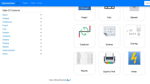
- The Software of Table of Contents is following of (Basics , Interface , Preferences , Project , Folio , Element , Conductor , Schema , Drawing , Reports , Export and print , Annex etc..)
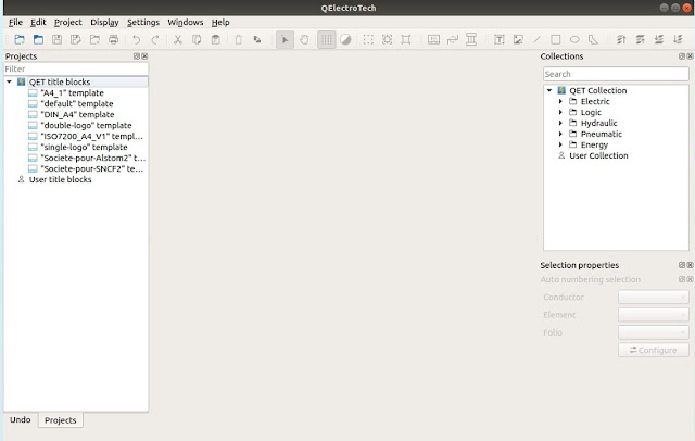
- The QElectro Tech Software contains many collections (Electrical , Logic , Hydraulic , Pneumatic and Energy symbols and Elements) also user can create they own symbols.
- Anyone can Access and Learn Electrical Diagram's using QElectro Tech Software.
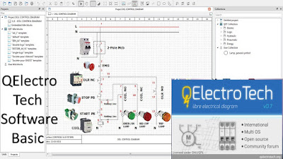
- Using this software to Draw the Electrical Power wiring and Control wiring easily also Draw the PLC Logic and Control wiring.
- After Install the QElectro software Components , Elements , and Symbols are Update Automatically.
- QElectroTech is an open source application to create electrical, electronics, automation, and control circuits.
- QElectro Tech has a large collection of standard and custom symbols, referred to as elements, that describe most of the commonly used components in electrical, hydraulic, pneumatic, computer systems.
- QElectro Tech also consists of an inbuilt element editor that permits creation of newer elements that do not exist in the collection.
- Elements in the collection are not editable i.e read only. But, once the element is drag dropped into a diagram, it is automatically added to imported collection in a duplicate copy.
- This copy of the element will be available for editing to effect suitable changes to create customized symbols.
- These elements can be selected drag dropped with mouse on to a diagram editor and connected with lines to represent or describe a system. A large number of such diagrams can be drafted under a project.
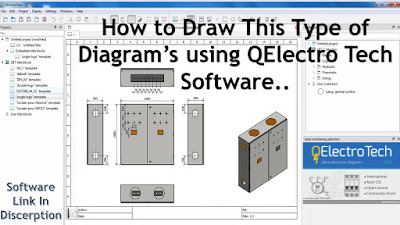
- The software can also be used to create mechanical objects to illustrate processes, instrumentation drawings among various creative possibilities.
- QElectro Tech is a good professional quality drafting application for various drawings that form a project.
1.
Click
the Windows [Start] button.
2.
Select All
Programs.
3.
Open QElectroTech program
group.
4.
Click
QElectroTech icon.
Once QElectro Tech has been launched, the main window looks as follow:
 |
| Main Menu |
Highlights:
- Libraries of common symbols are included along with the IEC 60617 standardized symbols.
- Elements are saved in an xml format.
- Export diagrams to formats including dxf, pdf, jpg, png, bmp, svg and more.
- Full screen mode.
- Highly configurable.
- Two tools are used as element editor for creating schematic symbols and a diagram editor for creating your drawings.
License and availability:
- QElectro Tech is under GNU/GPL license. It is currently available for Windows, Mac OS and Linux.
- QElectro Tech is a versatile and powerful tool for anyone involved in electrical design and documentation.
- Its open-source nature and active community make it a reliable choice for both professional and personal projects.
How to Get Started:
- Download the software from the official website or your platform's package manager.
- Explore the built-in tutorials and documentation to learn how to use the tools effectively.
- Start creating diagrams by dragging components from the library onto the workspace.
📥 Download QElectro Tech: Link
Key Features of QElectro Tech:
 |
Electrical Diagram Creation:
- Allows users to create detailed electrical schematics, including single-line diagrams, wiring diagrams, and control circuits.
- Supports a wide range of electrical symbols and components.
Customizable Elements:
- Users can create and customize their own symbols and elements to suit specific project requirements.
- Includes a library of pre defined symbols for common electrical components.
User-Friendly Interface:
- Intuitive and easy to use interface, making it accessible for both professionals and beginners.
- Drag and drop functionality for adding components to diagrams.
Multi-Platform Support:
- Available for Windows, Linux, and macOS, ensuring compatibility across different operating systems.
Export and Printing:
- Diagrams can be exported in various formats, including PDF, PNG, and SVG, for easy sharing and printing.
- Supports high quality printing for professional documentation.
Collaboration:
- Supports collaborative work, allowing multiple users to work on the same project.
Open Source:
- Being open-source, it is free to use, modify, and distribute, with an active community contributing to its development.
Use Cases:
- Industrial Applications: Designing control panels, PLC wiring diagrams, and industrial automation systems.
- Residential and Commercial Wiring: Creating wiring diagrams for buildings and infrastructure.
- Education: Teaching electrical engineering concepts and circuit design.
- Hobby Projects: Designing circuits for DIY electronics projects.
📌 Need more help? Drop your questions in the comments!
🔗 Connect with Me:
╰┈➤YouTube
╰┈➤Tumblr
╰┈➤Slide share
╰┈➤Quora
I hope you learnt something from this article📖
Please provide feedback on this article; this will help
me improve my feature Blog Post. 📝
Come look around, leave a comment, and contact us; I always like hearing from you.
Have a wonderful day.❤️
Thank you for visiting🙏


Very Useful Software Thank you this post
ReplyDeleteUseful
ReplyDelete